Journey of the Dream to Fly
In the last edition we learnt more about cockpit and pitot static systems in the cock pit.
Now we shall go ahead and look into Magnetic systems and Gyroscopic systems
Magnetic systems
consists of a magnetic compass, which perhaps is perhaps one of the oldest way to know directions using scientific instrument.
The compass shows the aircraft’s heading relative to magnetic north.
It is also seen that there may be variations between magnetic and true direction of the aircraft. This deviation is caused by electric current running in the wires of aircraft. (remember we have studied relation between electric current in wires and magnetism in our elementary school)
In order to overcome this and other complications the heading indicator is also used for aircraft operation, but periodically calibrated against the compass. Let’s understand more…
Gyroscopic systems
A gyroscope is a device used for measuring or maintaining orientation and angular velocity. we see use of gyroscope in our mobile phones as screen Auto rotate feature. Same is used in aircrafts to know the attitude (pitch), direction and turn of the Aircraft
Attitude Indicator
Just as we need to have a right attitude for progression in our lives, aircrafts also need to have the right attitude for safe flying.
Attitude for aircraft in simple words is defined as The orientation of an aircraft with respect to the horizon.
The attitude indicator (also known as an artificial horizon) shows the aircraft’s relation to the horizon. From this the pilot can tell whether the wings are level and if the aircraft nose is pointing above or below the horizon. Attitude is always presented to users in the unit degrees. The attitude indicator is a primary instrument for instrument flight and is also useful in conditions of poor visibility. Pilots are trained to use other instruments in combination should this instrument or its power fail.
Heading indicator

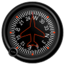
The heading indicator (also known as the directional gyro, or DG) displays the aircraft’s heading in compass points, and with respect to magnetic north when set with a compass. Bearing friction causes drift errors from precession, which must be periodically corrected by calibrating the instrument to the magnetic compass In many advanced aircraft (including almost all jet aircraft), the heading indicator is replaced by a horizontal situation indicator (HSI) which provides the same heading information, but also assists with navigation.
Turn indicator

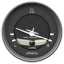
These include the Turn-and-Slip Indicator and the Turn Coordinator, which indicate rotation about the longitudinal axis. They include an inclinometer to indicate if the aircraft is in Coordinated flight, or in a Slip or Skid. Additional marks indicate a Standard rate turn.The turn rate is most commonly expressed in either degrees per second (deg/s) or minutes per turn (min/tr).
Lets take a look at a few videos to understand better…
In the next edition we will learn more about aircraft parts which assist in various motions of aircraft…….
By: Pradyumna Sharma (Sr. Manager – Ground Services)


